
In this article, I’ll show you how to use a photoresistor and an Arduino Nano to create fascinating timelapse footage with any resin printer.
In the world of FDM 3D printers, it is comparatively straightforward to make timelapse recordings these days. Modern printers offer the possibility to output a signal via a USB port that can be used to control a camera. This process can be implemented quite easily in the slicer program using a G-code during the layer change. However, with most resin 3D printers, this process is currently not so straightforward. Therefore, we have to take a little detour here and create a circuit or assemble it on a breadboard.
Curing of the resin in modern resin 3D printers is achieved by using a monochrome display in combination with a UV panel. Each individual layer of the printed object is shown on the display, with UV light shining precisely through the display pixels. This condition offers the possibility of scanning the UV panel with a sensor and, based on this, enabling control of a smartphone. For this task, one needs an inexpensive Bluetooth remote control, which is available for a few euros.

The intended goal is to trigger the remote control using an Arduino by simulating a button press at a specific time, namely exactly when the UV panel starts to glow. This requires opening the remote control and soldering two wires to specific locations. The remote control is best opened carefully with a cutter knife, since the plastic housing is usually not glued. The attached picture clearly illustrates to which contacts the wires should be connected.
The remote control has two buttons, one for iOS and one for Android. Before proceeding, it is recommended to check which of the two buttons is compatible with your smartphone. In my case, it turned out that the larger iOS button works with both an iPhone and a Samsung smartphone. Therefore, I decided to use the larger button.

To lead the cables out, two small recesses are milled on the housing with a Dremel.

The wiring diagram
The UV panel is scanned using a photoresistor (LDR). This LDR changes its resistance depending on how much light falls on it. Consequently, the LDR detects when the UV panel is turned on. The Arduino’s built-in analog-to-digital converter (ADC) then measures the change in the LDR’s resistance and responds accordingly through programming.
For all of this to work, a few components need to be linked together. The LDR receives a supply voltage of 5V. The resistance to be measured is determined by a voltage divider at A1 of the Arduino. For this a 10k Ohm resistor (R2) is needed.
The simulation of a keystroke is done with a NPN transistor like the BC547 or a similar model. This is controlled by a 1k Ohm resistor (R1) at pin D3 of the Arduino. The exact pinout on the Arduino does not matter as long as the correct pins are declared in the program.
The Bluetooth remote control is connected to one pin of the transistor and to GND.
As you can see, the construction of the circuit is relatively simple.

After I tested the circuit on the breadboard a small board was soldered.

Installation in the resin printer
In order for the photoresistor to scan the UV panel, it is necessary to guide it inside the printer. With my Anycubic Photon Mono X, this is very simple. You unscrew the side cover, drill a small 5mm hole and glue the photoresistor into it.


The Arduino code
To breathe life into it, we need a little Arduino code. I will try to explain the code here:
In the variable „ldrWert“, the current analog value of the LDR is measured, which corresponds to the „amount of light“ that is present at that moment.
If the analog value differs by 50 points, the program will branch into the first „if“ loop. Here the function „makepicture()“ is called to simulate a button press on the Bluetooth remote control. The variable „shot“ is needed to ensure that photos are not taken continuously while the UV panel is turned on. Only one photo should be taken per exposure cycle. Therefore the variable „shot“ is set to 1 and the program recognizes that one photo has just been taken.
The new analog output value of the LDR is now in the „light on“ state. When the UV panel turns off again, the new analog value of „ldrWert“ differs again and the variable „shot“ is reset to 0. The program now waits again for the opportunity to take a new photo.
It is indeed not always easy to translate code into words, but if you look at the code, you will probably be able to understand it easily.
int analogPin=1;
int shutterPin=3;
int ldrWert=0;
int ldrStart;
byte shot;

void setup() {
   Serial.begin(9600);
   shot = 0;
   pinMode(shutterPin, OUTPUT);
   ldrStart = analogRead(analogPin);
}

void loop() {
  ldrWert = analogRead(analogPin);

  if(shot == 0){
    if(ldrWert >= ldrStart + 50){
      ldrStart = analogRead(analogPin);
      delay(200);
      makepicture();
    }
  }

  if(shot == 1){
    if(ldrWert < ldrStart - 50){
      shot = 0;
      ldrStart = analogRead(analogPin);
      Serial.println("shot 0");
    }
  }

  Serial.print(ldrWert);
  Serial.print("    ");
  Serial.println(shot);
}

void makepicture(){
  digitalWrite(shutterPin, HIGH);
  delay(10);
  digitalWrite(shutterPin, LOW);
  shot = 1;
  Serial.println("make picture");
}
How to make timlapse videos with your smartphone
To create impressive time-lapse recordings with your smartphone, I recommend installing the „Open Camera“ app. During the test phase, we encountered problems with the original camera app, as it closed by itself after a certain time and thus interrupted the time-lapse recording. This problem was solved by using the „Open Camera“ app.
What makes this app special is that it is open source and offers a plethora of settings options. You can adjust a variety of settings according to your needs. Moreover, the app remains stably open even after hours of shooting without closing on its own. This makes Open Camera an excellent choice for time-lapse photography and provides the reliability you need.

Create a time-lapse video.
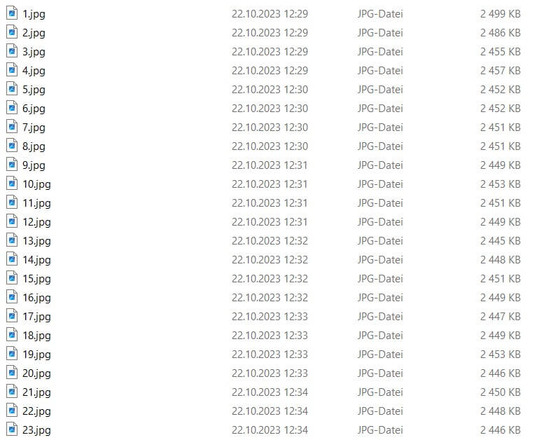
To create my timelapse videos, I like to use Davinci Resolve, a free program that is perfect for this. Once all the photos taken are numbered in ascending order, for example 1, 2, 3, etc., it is possible to select all the images and import them into Davinci Resolve in one step. In this case, the software automatically detects the sequence of images and creates a video from them. However, the problem is that a smartphone does not number the images in ascending order. In this case, it is necessary to name the images in ascending order.
To rename the images in ascending order, I have created a small Excel macro. Before you run the macro, it is necessary to sort the images in the folder by the „date taken“. Then you need to specify in the macro the folder path where the images are located. To start the macro, click the „Play“ button in the VBA editor. After running the macro, the photos are named in ascending order and can be easily imported into Davinci Resolve.
    'Excel Macro
Sub Photos_rename()
    Dim Pfad As String
    Dim Datei As String
    Dim Zähler As Long

    Pfad = "C:\Users\fraen\Documents\Fraens 2021\Youtube\Timelapse SLA Drucker\Eifel Turm\TL\" ' Change the path to the folder

    Zähler = 1

    ' Loop through all files in the folder
    Datei = Dir(Pfad & "IMG_*.jpg") ' Change the file extension as needed (e.g. *.jpg, *.png, etc.)

    Do While Datei <> ""
        Name Pfad & Datei As Pfad & Zähler & ".jpg"

        Datei = Dir
        Zähler = Zähler + 1
    Loop
End Sub

Conclusion
I would like to emphasize that the system works extremely reliably. The setup is relatively simple and inexpensive. Thanks to the „Open Camera“ app, it is possible to work continuously for many hours without interruptions of the Bluetooth signal and unwanted closing of the camera app. Everything runs smoothly, and I believe that this is the optimal method for creating time-lapse images with a resin printer.
It is important to note that this system is not exclusive to smartphones. Theoretically, the trigger signal could also be used to control an SLR camera, which opens up the possibility of creating even more impressive time-lapse images.


Wow, this piece of writing is pleasant, my younger sister is analyzing such things, therefore I am going to tell her.
You have a gift for explaining things in a way that’s easy to understand. Thanks for another great post!