The idea to make a 3D printed braiding machine came from my wife when she made a friendship bracelet with a kumihimo disc. Kumihimo discs are an important tool for kumihimo braiding, a traditional Japanese braiding art. These discs have indentations or cutouts that are used to arrange the threads in different patterns and designs during braiding. Kumihimo discs allow the production of both round braided structures and flat braided structures.
Kumihimo discs
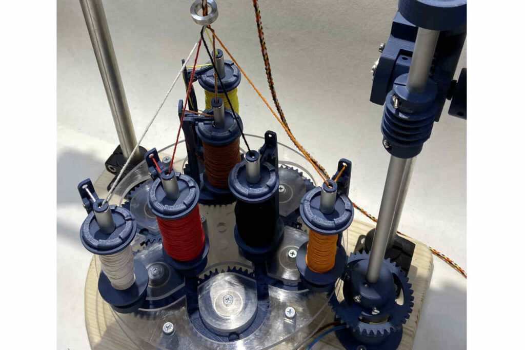
First Prototype from my Braiding machine
In 2022, I created my first design from a 3D printed braiding machine, which was extremely simple. It had the capacity to accommodate six spool carriers that circled in a track around the braiding point. This machine already laid the foundation for the basic design, which I later refined in my more advanced machine.
There was a HACKADAY article published about this machine.
24V gear motor
The first problems of the 3D printed braiding machine became apparent quite quickly. One of the problems is drive power of the DC motor. This was much too weak in the first prototype. The motor had 12V and a much too high speed. This meant that the torque was very low. For 6 spools it was just enough. In the new version, a 24V motor with a proper gearbox was installed. This easily manages to drive 6 spools. For 12 spool carriers, 2 24V motors should be installed.
Forces in the system
Forces in the spool carrier
Another important point that strongly influences the engine performance is the angle α (alpha). The smaller this angle becomes, the more torque acts around the pivot point (red). If the rope were to be pulled off completely vertically, the spool carrier would only move upwards. Due to the oblique force application, the spool carrier is pressed into the base plate. The smaller the angle, the higher the friction between the spool carrier and the base plate.
The angle is determined by the height of the braiding point. This is where all the ropes meet and form the braid. The height of the braiding point is in turn determined by the take-off speed of the finished braided rope. The slower the take-off speed, the lower the braiding point and the flatter the angle α.
A low braiding point has the advantage of producing a denser braid. If the take-off speed is increased, a coarse braid is produced. The following relationship applies: The slower the take-off speed, the denser the braid. This leads to increased friction between the spool carrier and the base plate. As a result, a higher drive power is required.
Another important point that greatly increases the drive power is the spring force Fs. I will explain later why this spring is needed. When the rope is pulled out of the spool carrier, a force Fr is needed. This force depends very much on the spring tension Fs. The higher the Fs, the higher the Fr. This greatly increases the force or motor power required to pull off the finished braid.
Small changes in the system, multiplied by the number of spool carriers, can have a significant impact on drive performance because of complex interactions between factors.
Braiding point
The rope tensioning mechanism
The spool carriers orbit the braid point, moving toward and away from the braid point during one revolution along the path of the base plate.
To achieve a clean braid, it is necessary that the rope is always kept under tension. This is ensured by the locking lever, which prevents the bobbin from rotating freely. During the braiding process, the rope is pulled out of the carrier. As the spool is blocked by the locking lever, the spring stretches apart. As soon as the spring is sufficiently tensioned and lifts the locking lever, the spool is released and the rope can be unwound. As a result, the spring relaxes again until the locking lever blocks the spool again.
If the spool carrier now moves towards the braiding point, the spring is released. Conversely, the spring is tensioned when the spool carrier moves away from the braiding point.
Spool carrier path and braiding point
Rope tension spring
Locking lever
Movement of the spool carrier
The spool carriers are moved by gear wheels along a sinusoidal path. These gears have recesses that can accommodate a screw head. With the aid of this screw head, the spool carriers are driven by the gear wheels. The recesses in two different gears always meet at the same point. This allows the spool carrier to be moved from one gear to the next.
This simple but ingenious principle allows the ropes to be intertwined.
Horn gears
The screw head fits into the recess of the horn gears
Extraction unit from the braiding machine
To drive the braiding process, a take-off unit is required to pull the rope out of the individual spool carriers. This take-off unit is driven by the same 24-volt motor that drives the horn gears. On the motor shaft is a worm gear, which in turn sets a spur gear in motion. The selection of gears in the spur gear determines the take-off speed.
The take-off speed is a crucial parameter in the braiding process, as it affects the braiding angle, i.e. the angle at which the ropes meet at the braiding point.
Slow take-off speed results in a dense braid with a flat braiding angle. Conversely, at high take-off speed, a coarse braid with a steeper braiding angle is produced.
Winding the spool
A decisive factor is the winding of the spool. To ensure a smooth process, the rope must not get caught. This is achieved by moving the rope back and forth during the winding process. This causes the rope windings to cross over each other continuously, which prevents the rope from getting stuck between the windings.
I plan to design a winding machine in the future that is suitable for these spools.
You can download the building plan here:
You will get the following digital files:
All .stl files you need to print the machine.
Assembly drawing in .dxf, .tif, .jpg, .pdf -format.
The complete 3D model of the machine in .step – format.
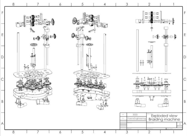
Exploded view drawings of the individual assemblies in .dxf, .tif, .jpg, .pdf – format.
The cut-out drawing of the base plate with the tracks in .dxf, .tif, .jpg format (incl. scale 1:1 drawing).
A drawing of all metal parts to be manufactured in .dxf, .tif, .jpg, .pdf – format.
A detailed parts list of all installed parts including internet links to the supplier.
WHY??? Admittedly, the idea of constructing a cigarette stuffing machine may sound rather special. The inspiration for it came to me during my wanderings through…